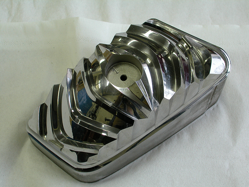
HiMill
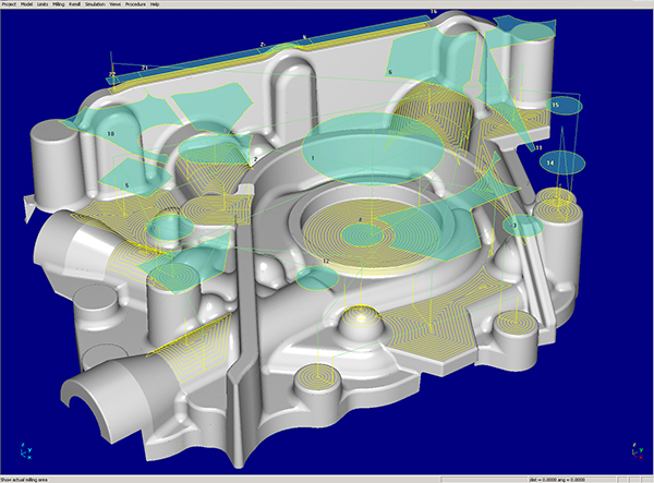
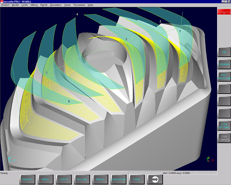
HiMill is the Fidia CAM 3D software for the manufacturing of moulds, dies, models and prototypes. It enables tool paths to be generated, from roughing out to super finishing, offering a wide choice of machining strategies starting from geometrically defined surfaces using CAD model as VDA-FS, IGES and CATIA format, ISO finishing programs or digitized surfaces.
HiMill the workshop CAM
HiMill is the software that produces tool paths for the milling of complex forms. Its simple and intrinsic approach adapts perfectly to the modern workshop while its solutions are expressly suited for complex and innovative technology such as that of High Speed.Thanks to its optional module HI-MILL is able to read clouds of points that describe the form of a physical object and are used for milling.
This applies to clouds of points obtained by scanning with an analog tracer, a laser or using optical systems. A specific algorithm has been specially developed in order manage large quantities of data efficiently.
Reverse engineering
HiMill transforms the elementary descriptive data for an object, expressed by means of X, Y and Z co-ordinates, into a skin structure written in the standard STL format and which can easily be interpreted by the most widely used Reverse Engineering systems.
3 axes + 2 easily programmable
With machine tools equipped with rotary heads, it is extremely important to already be able to program the positioning of the tool axis in space during the tool path calculation phase. In this way, the milling enjoys all the advantages of this programming, namely: a better use of spindle power, an optimum tool yield, a high surface quality and the ability to machine undercut zones.
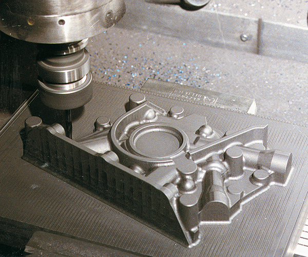
HiMill offers advanced solutions for this type of machining providing for, among other things, the definition of the starting rough shape (rough model) which is used during the processing of the roughing out operation so as to optimize the path by machining with the tool always in contact. The rough model can be updated after each tool path calculation in order to optimize subsequent processing.
Roughing out with HiMill: the most reliable solution
As well as spherical tools, HiMillL provides optimum management of cylindrical and toric tools. It is always possible to adjust the calculation accuracy of the pass that is in contact with the part in order to obtain a stock thickness that is as far as possible constant.
A preventive check on the dimensions of each individual milling zone is compared with the geometry of the tool specified so as to prevent any possible damage. A special algorithm with a high processing speed allows for the machining of very soft materials, as does the generation of roughing out operations with a high material removal rate. This completes the range of technologically advanced solutions for roughing out offered by HiMill.
High speed milling with HiMill
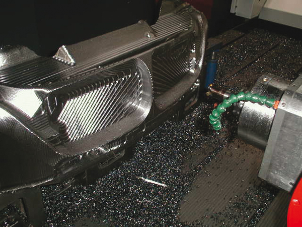
The HiMill CAM has from the outset been a highly recommended tool for generating high speed milling paths. The complexity of this technology means special attention is given to the way in which the tool moves and cuts into the material to be removed and traces its trajectories. Simple but effective options control entry of the tool into the material in any condition. HI-MILL is able to generate paths with no abrupt changes of direction e therefore particularly suited to high speed. With respect to the preceding machining, the software calculates each pass comprising the path in such a way that the removal of material is limited to the quantity specified by the user and generates, if necessary, several consecutive passes in order to complete the machining cycle.
The care with which the points are distributed along all the paths and their density have a positive effect on milling times and above all on the surface quality of the finished part.
The HiMill simulation module
HiMill incorporates a module for displaying the rough part that is derived from the simulation of individual paths calculated with any tool inclination. Any stock thickness is highlighted in colours that vary according to the quantity of residual material.
Photo gallery
CAD functions
HiMill is able to modify CAD objects forming the triangle model and to add new objects.
Transformation Functions:
- TRIM
- DELETE
- TRANSLATE
- ROTATE
- SCALE
BLANK
It enables to hide CAD objects by removing them from view (they become transparent). The hidden objects are however stored in the related file so that they can be later restored. The function to temporarily hide some objects is particularly useful to help to view and select objects placed on the background. After these operations, however, the hidden objects will have to be restored otherwise they will not be considered when calculating the tool path.
REVERSE NORMAL
For each selected surface, it inverts the normal vector’s direction, swapping face roles: front to back and vice-versa automatically updating colours. This, of course, influences offset operations.
OFFSET
Each selected surface is modified so that each point is translated along its related normal vector covering the set distance value. A positive value moves the points towards the vector’s direction a negative one moves them in the opposite direction.
Two offset modes are available:
- Absolute: the specified value expresses the offset according to the surface’s original dimensions when its offset was zero.
- Relative: the specified value expresses the offset according to the surface’s effective shape. This is the most frequent used mode.
Creation of new cad objects
HiMill enables to add to the model new flat surfaces parallel to the XY plane of different shapes (rectangular, circular, polygonal). Such surfaces can be employed to cover, for example, any possible faults on the input files used to outline the project, or to protect a file from any unwanted modifications.
ENTITY ANALYSIS
By the means of this menu option it is possible to have information concerning entities on the CAD model. Information may be linked to a specific or generic entity according to the two options provided.
UNDO-REDO
Effects of commands made within a CAD session (cancellation, insertions, modifications) can be deleted thanks to an “undo” mechanism allowing to go back, step by step, right to the moment of the session CAD entry. A corresponding “redo” mechanism enables to correct any possible mistakes in the “undo” process.

