Isograph: The CAD/CAM 2D½
With the innovative user interface, profiles can be defined by simply using the softkeys and mouse. Interaction is, therefore, easy and immediate even for operators with no specific programming knowledge. A wide range of fixed drilling cycles and complex cycles for the pocket milling of any profile complete the package.
ISOGRAPH is a 2½D CAD/CAM with a highly innovative user interface that is especially suited to the workshop environment. It is ideal when machining operations must be programmed and executed rapidly, such as the machining of pockets, smoothing, machining of profiles, drilling, boring. Isograph can be perfectly integrated on the FIDIA Numerical Control, but its potential can also be appreciated in stand-alone use on an ordinary Personal Computer. The use of soft keys and the mouse allow for easy and immediate interaction by all operators, with no specific knowledge of programming being required.
ISOGRAPH can be used to:
- define geometric profiles
- manage ISO files
- import geometric elements written in DWG/DXF formats
- import files written in IGES format
- employ a powerful programming language
- generate contouring of open or closed profiles
- generate paths for re-machining of residual material
- generate fixed drilling, tapping and boring cycles
- machine pockets with a rectangular, circular or general profile
- generate smoothing cycles from the dialogue window
- write and simulate CNC procedures
Defining profiles
ISOGRAPH is equipped with a powerful and intuitive GRAPHICS EDITOR for defining geometric elements and profiles. The operator has no need to learn a specific programming language or the syntax of particular ISO functions. The soft keys guide him, by means of icons, as he defines the geometric profiles. Rotations, offset and translations can also be applied to the profiles.
Machining profiles
Profiles, however defined (ISO, Graphics Editor, DWG/DXF), can be compensated on one of the main planes, or on any positioned plane. 2D radius compensation on any reference plane can also be applied to profiles defined in 3D. Compensation of the profile can be repeated on more than one level to allow for the machining of complex walls. Once the necessary technological parameters have been entered, ISOGRAPH generates the tool path in complete safety thanks to its tested anti-collision algorithms.
Re-machining profiles
After generating tool radius compensation of a profile, ISOGRAPH automatically identifies zones where there is residual material. Appropriate re-machining paths, using progressively smaller tools, can be defined simply and intuitively. Also re-machining paths can be repeated on more than level.
DXF/DWG and IGES reading
ISOGRAPH imports maths written in DWG/DXF and IGES formats. ISOGRAPH enables to machine its own profiles: generating tool radius compensation paths, re-machining of residual material, pocket machining and to associate fixed cycles (G82, G83, etc.) to elementary geometric elements. ISOGRAPH simplifies complex maths thanks to its layer management (logic programming levels).
Fixed cycles
ISOGRAPH is equipped with a wide range of fixed cycles:
- drilling (G82, G83, G182, G183)
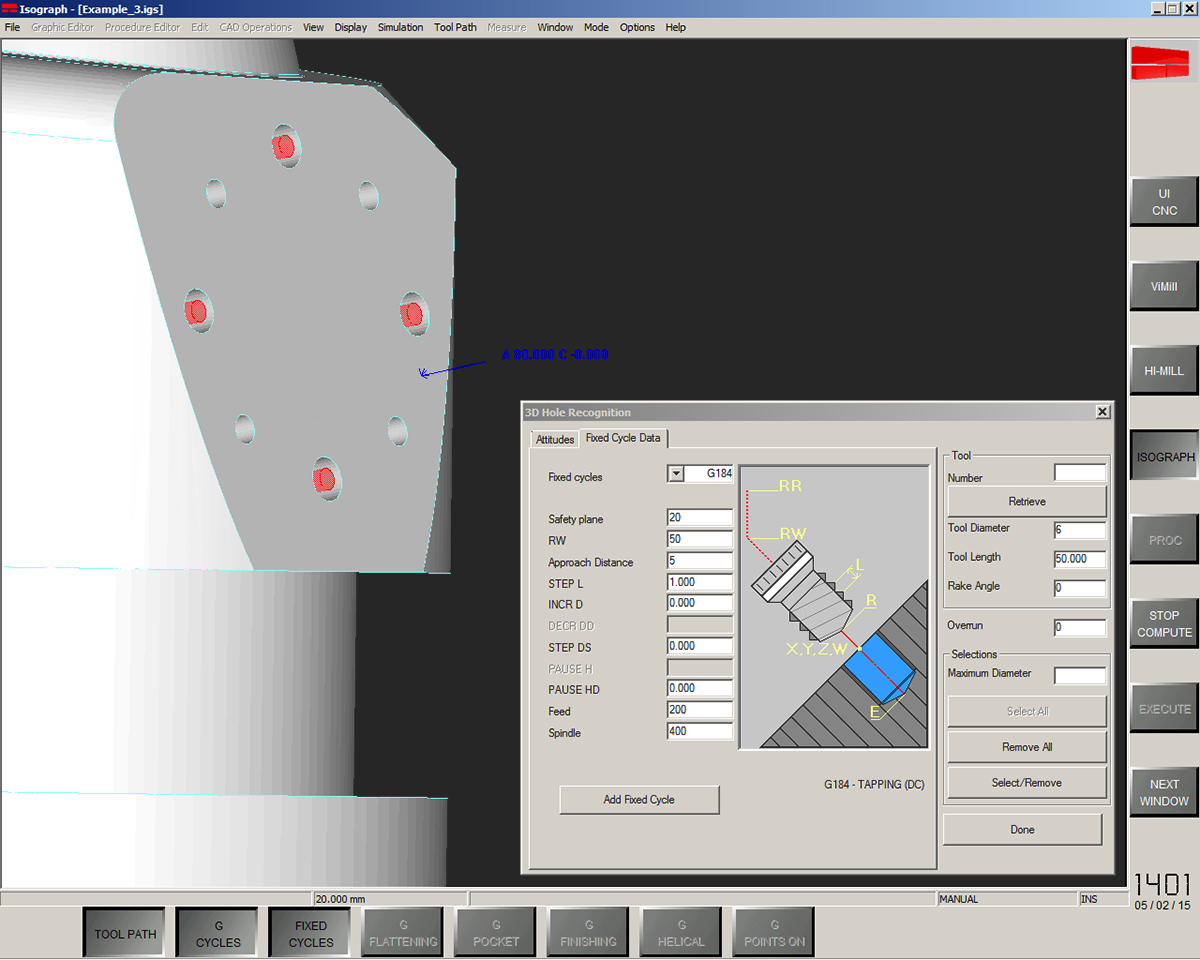
- tapping (G84, G184)
- boring (G85, G86, G185, G186)
- deep drilling (G282)
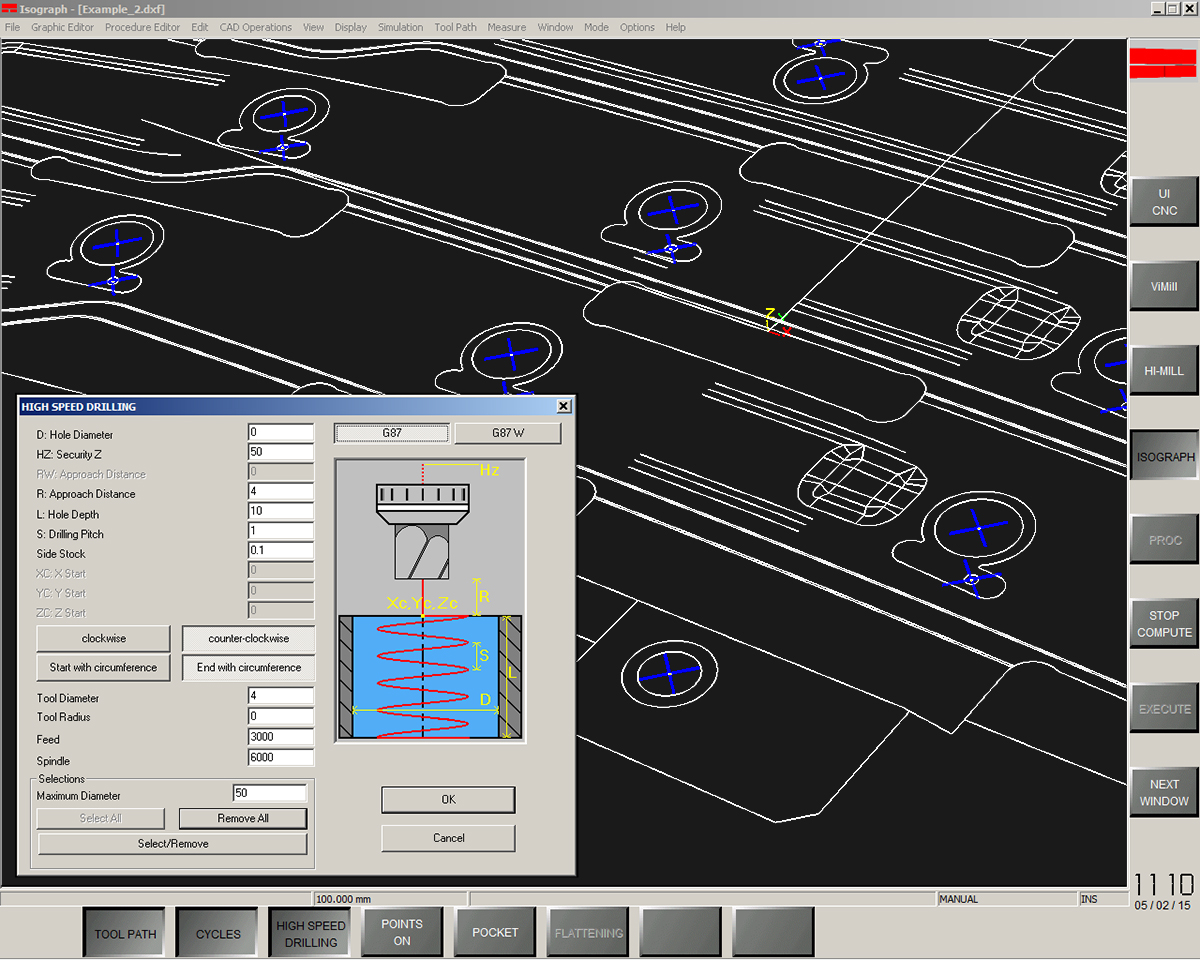
- helical drilling for high speed
Any fixed cycle can be repeated at specified intervals along a profile or applied to all the elementary entities selected by the operator.
Recognition of holes
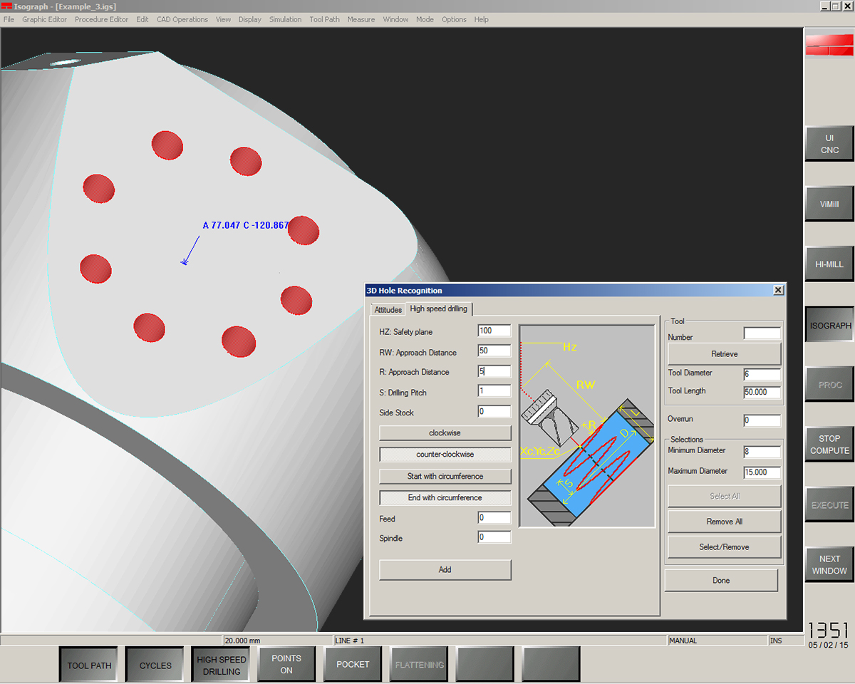
Furthermore the recognition of holes in the IGES format is also available for the automatic definition of the hole’s first and last values both on the working planes (G17, G18, G19) and on any inclined planes.
Pocket machining
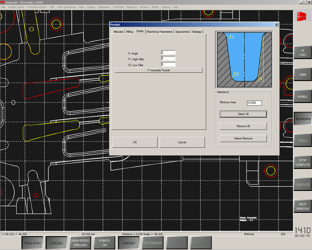
Machining pockets using ISOGRAPH is particularly efficient owing to the powerful operator interface that enables the following to be defined:
- the profile to be machined (circular, rectangular, straight/circular slots or generic),
- depth and inclination of side walls,
- machining strategy (contouring or zigzag),
- machining typology (roughing or finishing),
- technological parameters for the generation of tool paths,
- the tool’s most appropriate approach,
- machining allowance on pocket sides and bottom.
It is also possible to generate paths with no abrupt changes of direction that are particularly suited to high speed.
Pocket identification
Identification of pockets in the IGES format is available and possible both on the working planes (G17,G18 e G19) and on the inclined planes. Within one attitude more than one pocket can be machined both in roughing and finishing modes. Should the IGES file contain surface descriptions, the pocket geometric shall be identified directly on the maths. It is therefore possible to identify and manage pockets in any section. Any possible internal slots shall be identified and automatically excluded from the machining.
Management of CNC procedures
ISOGRAPH makes available a powerful environment for the management of CNC Procedures. Detailed dialogue windows enable parameters and commands to be written in a Procedure and modified, avoiding syntax errors. When the Procedure is complete, and before execution on the machine tool, ISOGRAPH simulates its operation indicating any problems.


