


Fidia makes the difference
For over 40 years, Fidia has brought innovation to the world of machining. With its numerical controls, Fidia has introduced solutions that have profoundly transformed production processes. Today, with its continuous Research and Development activity and careful analysis of Client requirements, Fidia remains a reference for the industry worldwide.
News
- All
- Choice guide
- Company
- Events
- HSM Machines
- InForm
- Investor relations
- News
- Press release
- Products
- Uncategorized

MTD Events – EMO Hannover 2023
Can your head measure and compensate for geometric errors? Rowan talks us through Fidia Spa and what you can expect from our stand. At the Fidia stand, you will have the opportunity to discover the latest updates on their new range of Fidia Numerical Controls suitable for high-speed machining in the aerospace, automotive, and energy industries. One of the highlights is the new DL321 compact 5-axis high-speed gantry with linear motor technology for processing various materials such as steel and aluminum alloys. It features an innovative design with a 45° rotated RAM for greater rigidity and improved thermal-symmetrical behavior as well as much much more!
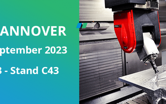
EMO Hannover 2023
Fidia at EMO Hannover 2023: September 18-23 We look forward to seeing you at EMO Hannover from September 18th to 23rd, the world's leading trade fair for the mechanical engineering industry. At the Fidia stand, you will have the opportunity to discover the latest updates on our new range of Fidia Numerical Controls suitable for high-speed machining in the aerospace, automotive, and energy industries. One of our highlights is the new DL321 compact 5-axis high-speed gantry with linear motor technology for processing various materials such as steel and aluminum alloys. It features an innovative design with a 45° rotated RAM for greater rigidity and
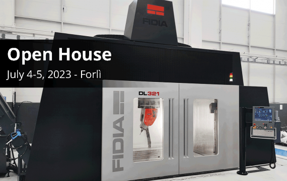
Open House 2023
Fidia Open House, July 4th - 5th, 2023! We are pleased to announce the Open House organized by Fidia, which will take place from July 4th to July 5th, 2023, at our prestigious manufacturing facility located at 76 Balzella Street, Forlì - Italy. During this event, you will have the opportunity to witness live machining demonstrations showcasing the latest innovative technology applied to the various models of machines displayed, including the new generation of DL321 Gantry machines. For more details, please click here or contact our event team. We look forward to welcoming you to our Open House event! news

