I/O LINE
Programmable I/O
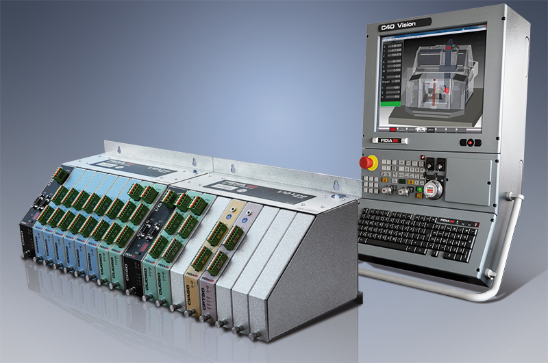
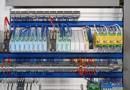
The new Fidia I/O Line™ is the latest generation of input/output; designed to be installed inside the machine tool electrical cabinet they are connected to the numerical control through the Fidia FFB bus.
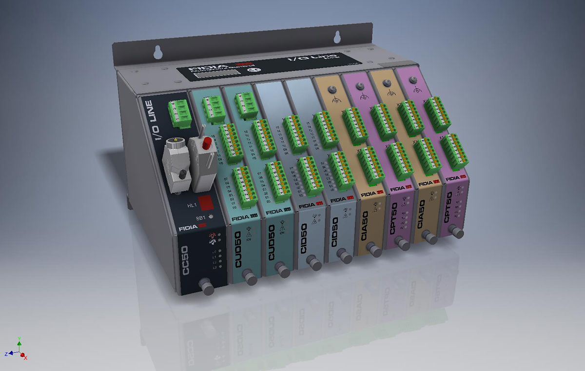
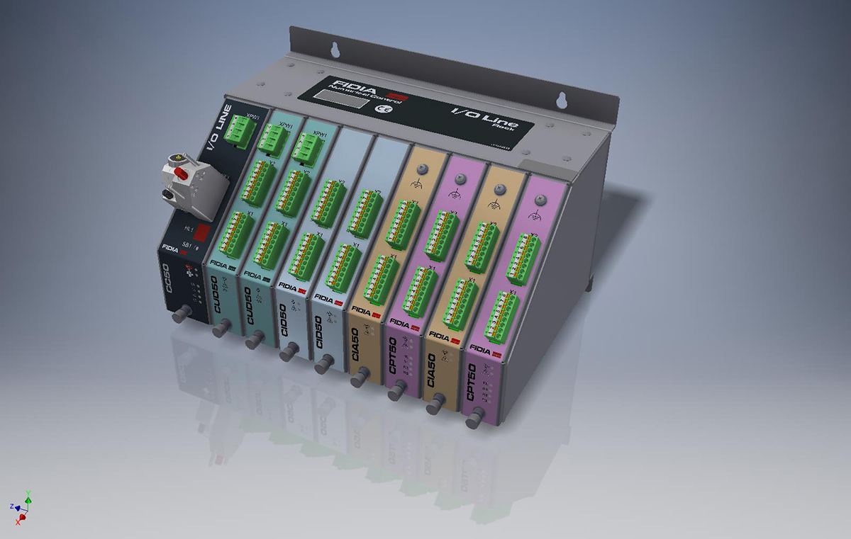
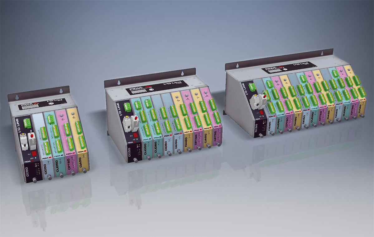
In order to grant the maximum flexibility while minimizing the space in the electrical cabinet, the I/O Line™ range offers three different rack models, all equipped with the interface to the Fidia FBB bus (CC50).
Depending on size, each rack can host either 4, 8 or 12 I/O Line™ modules. Up to a maximum of 32 I/O Line™ racks in different sizes can be combined in the same system and host different types of I/O Line™ interfaces to comply with each single application requirements.
The metallic chassis of I/O Line™ module, fixed on the wall of the electrical cabinet of the machine, ensures a high immunity to electromagnetic disturbance for the whole system.
Design
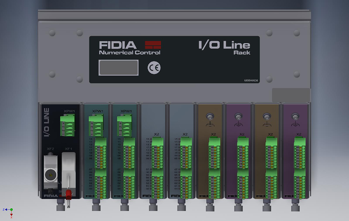
The design of the chassis and boards of the I/O Line™ modules has been carefully conceived to make wiring, maintenance and diagnostics even more simple and easy.
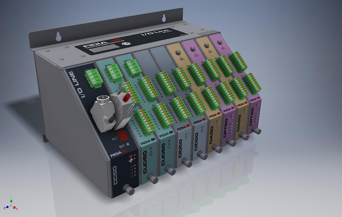
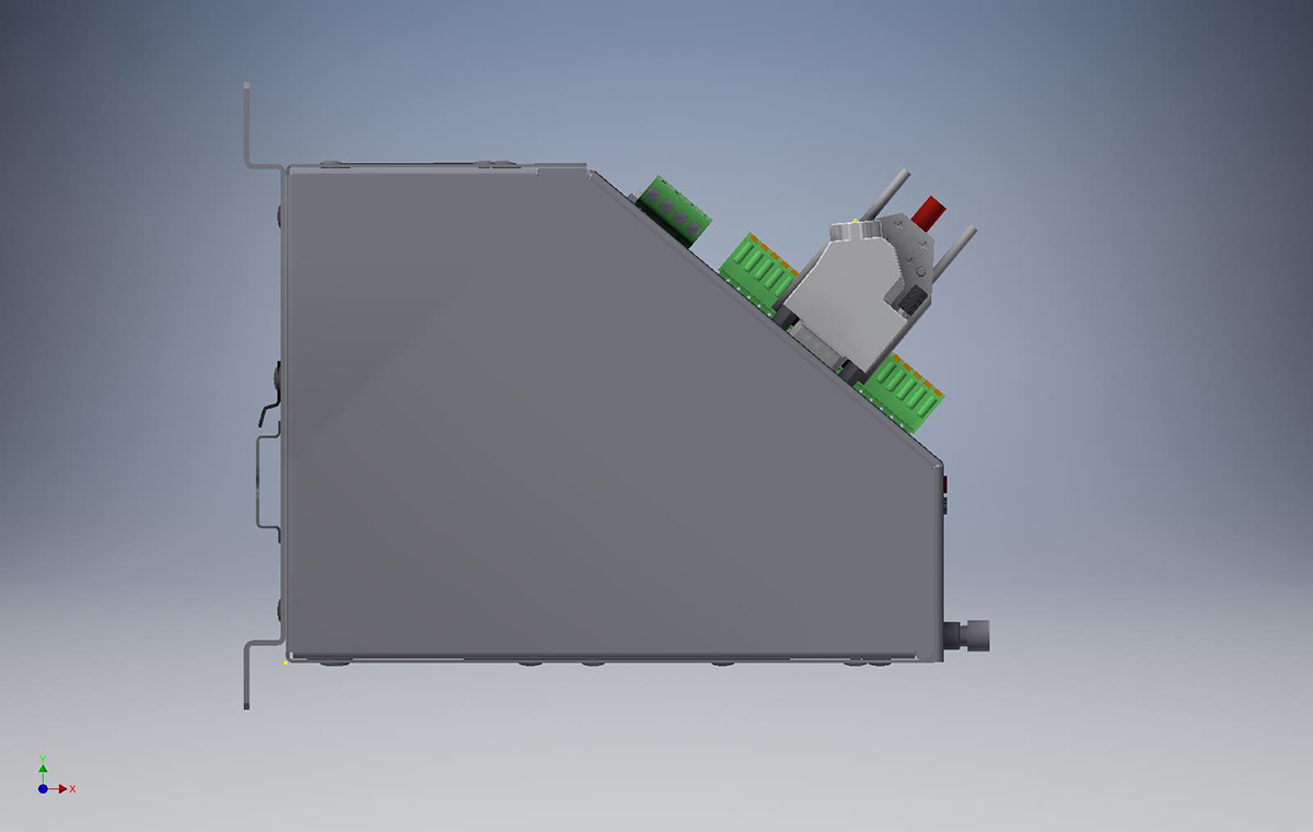
The front position of interface board connectors and terminals, positioned at the right distance from the base of the panel, together with the angled outlet for the wiring, enables wiring installers and maintenance engineers to work efficiently, even with a high density of components inside the electrical panel.
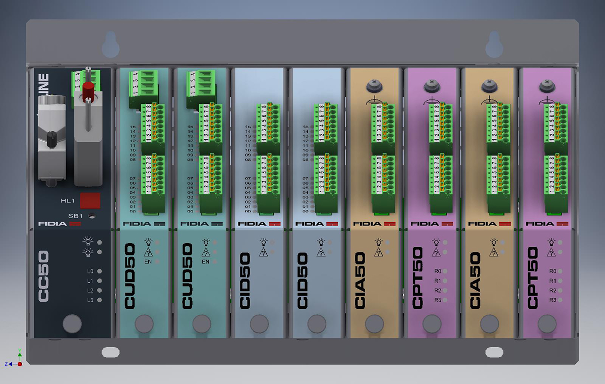
The front position of the signal and diagnostics LED enables a prompt checking of the board and signal status
Architecture
Compared to the previous generation, the I/O Line™ cuttingedge architecture has been strongly enhanced, ensuring a considerable improvement in terms of performance and reliability.
The numerical control directly accesses the I/O Line™ modules via the FFB bus and the CC50 coupling board with the same sampling time used for the axis drives, thus significantly reducing the access time.
A further advantage of direct numerical control access to interface boards is the improved accuracy and promptness with which it is possible to diagnose any malfunctions of each single I/O board
Photo gallery
Technical data
| Name | Description | Notes |
| CC50 | FFB bus interface board | |
| CID50 | 16 24V DC digital inputs | |
| CUD50 | 16 24VDC 500mA digital outputs | 4 outputs boosted to 24V DC 2A |
| CIA50 | 4 analogue inputs, 16-bit resolution, input voltage range 0-5V, 0-10V, -5V-5V, -10V-10V | The input voltage range can be independently programmed via software for the four channels |
| CPT50 | 2 inputs to measure RTD, type PT100 or PT1000, 0.1°C resolution, 2-, 3-, or 4-wire connection | The RTD type and connection configuration can be independently programmed via software for the two channels |
| SLU50 | 2 RS-232 or RS-422 serial lines to interface with the serialised Fidia button pad or generic serial devices. 2 digital inputs | The protocol type and communications parameters can be independently programmed via software for the two channels. For digital probes or laser tool pre-set device. |
The new interface boards for CID50 digital inputs offer 16 input channels with high resolution to identify variations in the input signal status.
The new interface boards for CUD50 digital outputs offer 16 output channels, 12 of which with rated output current of 500mA and 4 channels with rated output current of 2A.
The new interface boards for CIA50 analogue inputs offer 4 input channels with an input voltage range that can be selected via software and with 16 bit resolution.
The new interface boards for CPT50 temperature sensors offer two channels to interface with the PT100 or PT1000 temperature sensors with 2, 3 or 4 wire connections; the sensor type and connection configurations are independent for each channel and can be configured via software.
The new interface board for the SLU50 serial lines offers two interface channels for multi-protocol serial communications (RS-232 or RS-422); the protocol and relevant communications parameters can be configured via software.
On the same board 2 inputs for digital probes or laser tool pre-set devices are available and can be configured by software according to the type of signal. The system’s high degree of flexibility and the possibility to configure by software the interface boards, allow standardised hardware configurations and minimisation of parts in stock.


