nC19 ACL enhanced
Fidia presents the new nC19 ACL enhanced numerical control. A NC that combines a high level of quality with compact design while benefiting from all the Fidia technology including the new ACL adaptive logic.
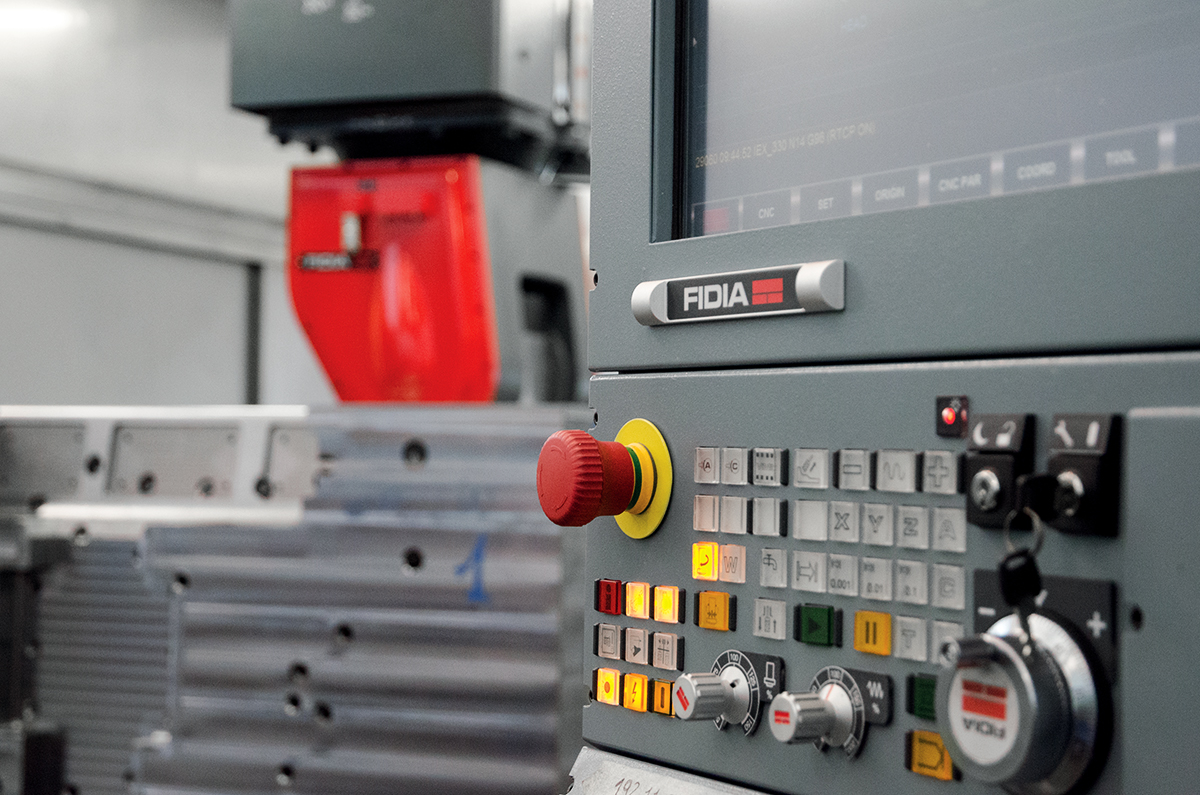
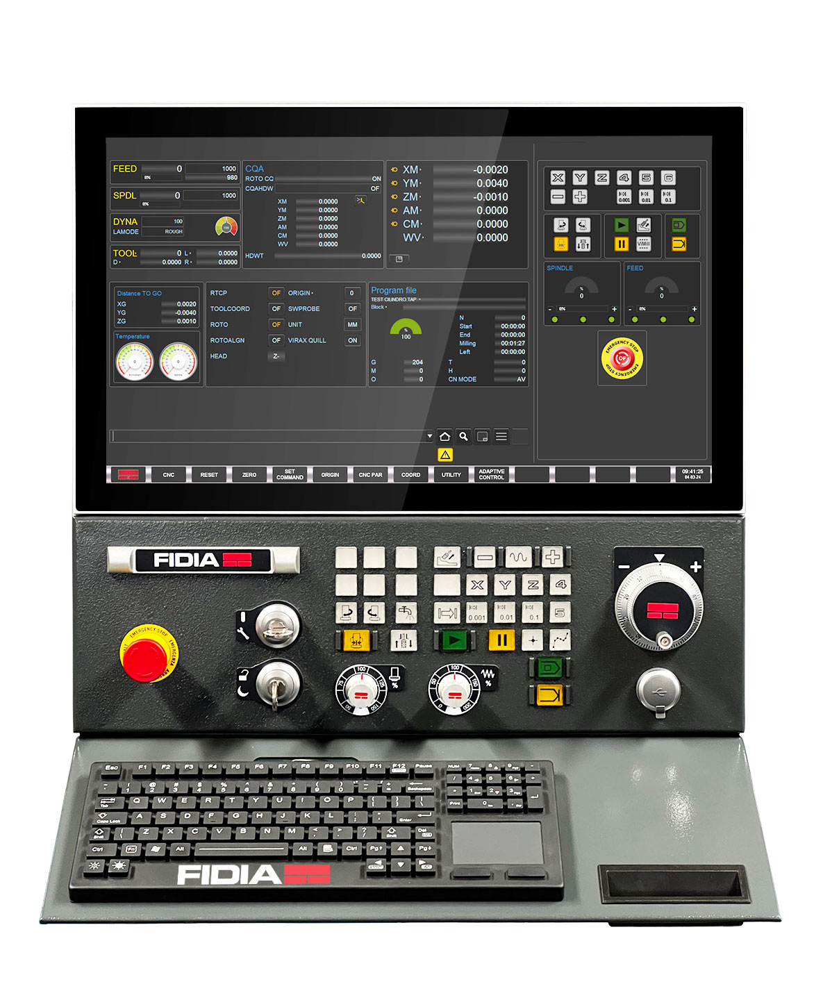
Designed to be extremely compact and versatile, it adopts a newly developed physical keyboard and button panel that increase usability and ergonomics, as well as an 18.5" wide P-CAP multi-touch full HD screen.
In search of increasingly complete solutions to equip modern machine tools, Fidia has created, with the nC19 numerical control, a compact and functional solution that optimizes the supply of the electronic part. All this while maintaining the essential features of the performance that have characterized the Fidia brand for 50 years: fast and precise execution of 3D paths, management of 5 interpolated axes, advanced functions for the processing of molds and models, openness to Windows applications.
Cam Machining
 Network file transfer
The NC integrated network card and the Windows® 7 Ultimate operating system allow for an easy introduction of the nC19™ control into the company network. All CAM engineering programs can be therefore directly stored into the NC hard disk. A USB port located on the NC front-end allow the execution of part-program even in case of network unavailability.
3D Graphic visualization
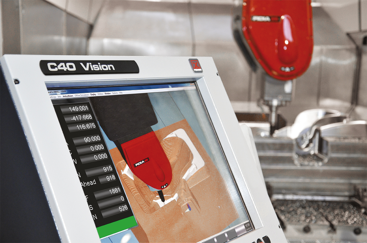
An optimized and even simultaneous visualization for displaying large and different format files enables a quick check of the milling path. Its main features as follows:
- visualization of the mathematical model laid upon the tool path;
- display of multiple paths marked with different colors;
- vertex coordinates measurements, distance between two points and angle formed by two segments for each loaded tool path;
- management of ISO - DXF - IGES - STL - VDA - FS - PRJ (HIMILL project) formats.
Parameters and procedures
Roto-translation, scale factors, axis change, change of origins, change of machine, movement release clearance etc., can be directly activated or modified by the operator on the NC without modifying the part-program created by the CAM. In addition to this, where changes are to be applied with a specific sequence on file parts or on several files, the programming through Procedures is provided allowing for an easy and maximum automation of part program sequences thus resulting in maximum efficiency.
Graphical environment
Data entry for milling or drilling programming is done with the aid of graphics and explanatory texts for an easier input of all necessary parameters so as to create the desired machining cycle. Each program block or work cycle is clearly displayed graphically in 2D or 3D view in order to expedite the operator in achieving the required processing. Cycles are planned specifically for the rectangular, circular or slot pocket machining for the rectangular or circular flattening, further to the several drilling cycles: for all of them a useful graphic help to programming is provided. The “help on line” function is also constantly available and this allows for a quick reference of the use and programming manual directly displayed on the NC screen.
ISOGRAPH™
For the machining of more complex components or to simplify the geometric definition of profiles, ISOGRAPH™ offers a wide range of functions and dedicated cycles. A powerful graphic editor allows to define straight lines, circles and points thus drawing profiles, placing fillets and chamfers, applying tool radius compensation and also inserting approaches. The above operations are performed simply by pressing the function keys and the matched dialog boxes: there is no need to remember any programming function and related syntax. The pocket working cycle allows for the management of complex geometrical profiles; for the rectangular pockets it enables several side wall inclinations and also different radius and fillet of pocket profiles and sections. The radius compensation through the ISOGRAPH™ dialog box grants an automatic approach and exit to and from the profile. It even enables the machining on open profiles by calculating several tool path levels. Furthermore it performs automatically the removal of any residual material. For drilling cycles, in addition to the definition of the points on grid and circumference, the definition of the points on a generic profile is provided.
DXF project management
Programming from a drawing can be a source of errors for a misinterpretation or simply for errors made in the writing process (e.g. to perform 100 holes, a hundred program lines have to be written). Direct reading of DXF files in ISOGRAPH™ environment helps avoiding such errors and it also simplifies the milling and drilling programming. The graphical interface enables the management of DXF files by selecting the items to be processed. To make an example, for the drilling operations it is possible to specify the diameter of th e required holes or to define the min/ max diameters and even exclude some specific items. Once the selection is over a fixed cycle has to be matched with the holes and the drilling program will be automatically generated. The same process can be used for profiles where the ISOGRAPH™ radius compensation will be applied to the selected profile. The DXF drawing can be shifted or rotated so as to position the origin at best for the processing to come.
CNC options
Piece alignment
To avoid time-wasting operations on the machine it may be useful to use the FIDIA piece alignment features. To this purpose some specific dialog pages with graphic support can guide the operator in calculating and activating the suitable rotations. The alignment cycles can be performed with digital probes or more simply with a tool: in the latter case the points have to be collected manually. Several cycles are provided referring to the geometrical elements available on the piece: working surface, holes, pins. On machines with swivelling head, rotation for piece alignment may also be applied to rotary axis, so that even in 5-axis paths the tool will keep the proper orientation in relation to the piece.
Tool table
The tool table completion can be performed directly on the machine or it can be done externally and then transmitted to the NC via the network or via the USB port. In fact, the tool table may be compared to an Excel file that can be consequently imported from an outer device; in a similar way, once completed, it may be saved and exported. In addition to the standard uses such as diameter, radius and length, some new fields can be added whose management is assigned to the PLC. The combination with the tool identification systems results particularly useful within a tool centralized management.
Piece measurement
For a checking of the produced piece the use of measure probes on the machine tool is more and more frequent. Fidia offers cycles for elementary and geometrical measuring as well as cycles for measuring surface points that allow to take advantage from the most popular 3D measurement software. The Fidia single point measurement cycle provides for the management of the approaching vector perpendicular to the normal to the measuring point thus simplifying the interfacing with the measurement software.
Tool measurement
The Fidia TMSC laser device is the optimal solution to measure and check the tools on the machine. The use of a focused beam laser system guarantees high precision even with small diameters (up to 0.1 mm). The integrated software on Fidia NCs provides 16 differently shaped tool types (spherical, torical, cylindrical, conical, with inserts, grinding wheels, etc..).
Technical specifications
| Technical data | nC19 |
| Processor | Intel® 2,9 GHz dual core + Power Pc 64 bit |
| RAM | 4GB |
| Hard disk | SSD 120 GB |
| Operative System | Windows 10 IoT Enterprise 2019 LTSC |
| Monitor | 18.5" WIDE LCD TFT, 16:9 (1920x1080), P-CAP, multi-touch |
| Interpolated Axis (max) | 15 + 1 Mandrino (singolo canale) |
| Overall dimension (HxWxD) | 434 x 461 x 198 mm |
| Overall dimension with keyboard support (HxWxD) | 516 x 461 x 360 mm |
| Supply Voltage | 24V |
| Power consumption | 80W |
| Weight | 23Kg |


